
General
Sheet Metal DFM: How AI Handles Bend Radius, K-Factor, and Manufacturing Cost Optimization
A mechanical engineer's guide to AI-powered sheet metal DFM, covering bend radius validation, k-factor accuracy, flat pattern generation, and cost optimization before parts go to fab.
·
⏱
5 min read

Michelle Ben-David
Mechanical Engineer · B.Sc. Technion
Ex-Officer, Elite Tech Unit · Aerospace & Defence · Medical Devices
Michelle Ben-David is a mechanical engineer and Technion graduate. She served in an IDF elite technology and intelligence unit, where she developed multidisciplinary systems integrating mechanics, electronics, and advanced algorithms. Her engineering background spans robotics, medical devices, and automotive systems.


BOTTOM LINE
AI-powered fastener selection cross-checks geometry, material, thread engagement, torque requirements, and your approved vendor list in seconds — eliminating the back-and-forth that adds days to assembly design cycles.
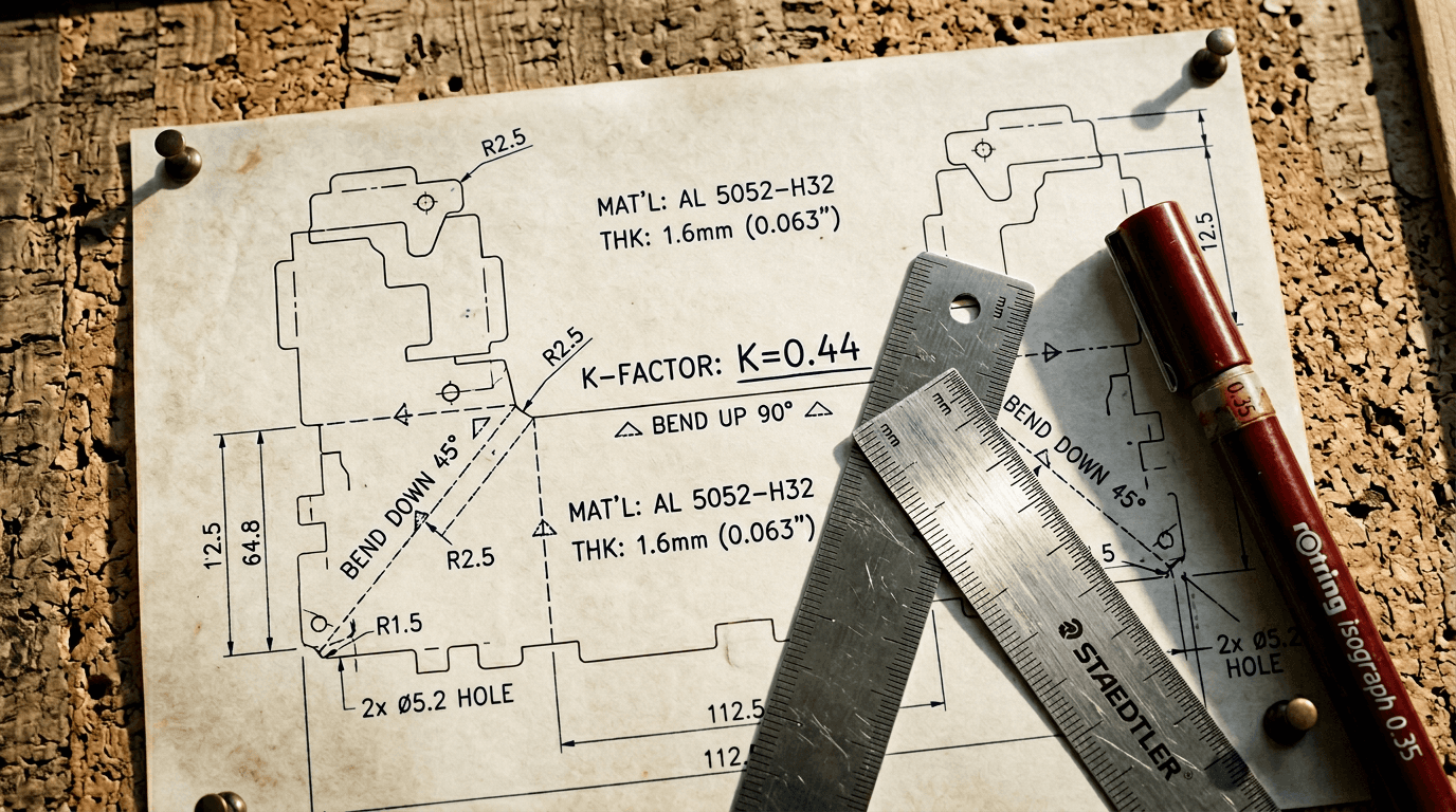
Sheet Metal DFM Is a Geometry Problem
Sheet metal fabrication failures are almost entirely geometry-based. The material and the process are well understood. The failure modes are documented. Minimum bend radius tables exist for every common alloy and temper. Hole-to-bend clearance rules are calculable. Flat pattern interference is a geometric fact that can be checked before the file goes to the laser.
The reason these failures still reach fabrication is not that engineers do not know the rules. It is that checking every feature on every part against every applicable rule, at the pace of a real design cycle, does not happen consistently without a tool that does it automatically.
The Sheet Metal DFM Checks That Matter
Bend Radius Validation
Minimum bend radius for sheet metal is a function of material, temper, thickness, and the bend direction relative to the grain of the sheet. Inside bend radius below the minimum for the specified material and thickness causes cracking at the outer surface of the bend. The minimums are published by material suppliers and covered in standards.
AI inspection reads the modeled inside radius on every bend feature and compares it against the minimum for the specified material and thickness. It flags violations with the specific radius, the minimum required, and the source standard or internal guideline cited.
This is straightforward to check manually on a part with three bends. It is not straightforward on a complex enclosure with 40 bend features across six faces.
K-Factor Accuracy
K-factor describes where the neutral axis sits within the material during bending, as a ratio of the neutral axis position to the material thickness. It directly affects flat pattern dimensions: use the wrong k-factor and your flat pattern is wrong, which means your part does not conform to the 3D model after forming.
The correct k-factor depends on material, thickness, bend radius, and your specific tooling setup. Most CAD tools use a default k-factor that is approximately correct for common mild steel at typical thicknesses. For aluminum, stainless, high-strength steel, or non-standard thicknesses, the default is often wrong.
AI tools connected to your fabricator's process data or your internal manufacturing guidelines can apply the correct k-factor for the specified material, flag when the CAD default is being used for a material where it is not accurate, and calculate the correct flat pattern length.
Hole-to-Bend Clearance
Holes too close to a bend distort during forming. The minimum clearance is typically expressed as a multiple of material thickness plus bend radius. A hole at 1.5 times material thickness from the bend tangent line in 3mm steel is going to distort. The rule is calculable. AI checks every hole on every part against the applicable clearance rule.
Flat Pattern Interference and Grain Direction
Flat pattern interference occurs when a feature in the flat pattern overlaps or conflicts with another feature, which only becomes visible when the 3D model is unfolded. AI tools that read the geometry can unfold the flat pattern computationally and check for interference before the file goes out.
Grain direction matters for bending performance in aluminum and some stainless alloys. AI inspection can flag bends oriented parallel to the rolling direction on materials where perpendicular orientation is required for crack-free bending.
Feature-Specific Checks
Relief cuts at bend terminations. Minimum flange lengths for press brake tooling access. Tab and slot alignment for welded assemblies. Countersink depth versus material thickness. Each of these is a geometric check that AI handles the same way: compare the modeled geometry against the rule, flag violations with citations.
IN PRACTICE · HP ENGINEERING TEAM
"We had a senior engineer leave after 11 years. Within two weeks, the team was querying his documentation through Leo like he was still there. That's when we knew this was different."
— Senior Mechanical Engineering Manager, HP Inc.
Manufacturing Cost Optimization
DFM inspection catches problems. Cost optimization identifies opportunities. For sheet metal, the main cost drivers are material utilization, setup time per part, number of bends and their sequencing, secondary operations (tapping, hardware insertion, welding), and tolerances tighter than the process requires.
AI tools that connect to your fabricator's pricing data or internal cost models can flag over-specified tolerances, suggest bend sequence reordering that reduces setup time, identify features requiring secondary operations that could be eliminated by design changes, and compare alternative material and thickness combinations against the functional requirements.
At ZutaCore, Leo's design suggestions identified a standardized approach to a recurring part type that eliminated custom design work per project and yielded $400 per unit in direct manufacturing cost savings. The mechanism was straightforward: AI identified that a standardized adjustable design using off-the-shelf parts solved the same functional requirement as a series of custom parts.

What This Looks Like in Practice
Scenario: Sheet metal enclosure for industrial electronics, prototype to production transition
Prototype parts were laser-cut and brake-formed in small quantities. Transitioning to production with a contract sheet metal fabricator. The fabricator's DFM review comes back with six issues: two bend radii below minimum for the specified aluminum alloy and temper, three holes within distortion distance of bend lines, and a tight tolerance on a formed feature that requires a secondary operation.
Three of those six issues are on features that an AI inspection would have caught in the design phase. The bend radius minimums for aluminum 5052-H32 are published. The hole-to-bend clearance rule is calculable from the part thickness. Catching them before the prototype build does not change the prototype outcome, but it eliminates the feedback loop iteration before production release.
With Leo AI in the pre-release workflow: engineer runs Leo Inspect on the enclosure before sending to prototype. Two bend radius violations flagged against the aluminum alloy minimum, citing the relevant material specification. Three hole proximity issues flagged with the applicable clearance calculation. Engineer addresses all five in the design phase. Prototype and production drawing are consistent. Fabricator's DFM review focuses on process optimization rather than geometry corrections.
Run a Sheet Metal DFM Inspection on Your Parts
Bring a sheet metal part or enclosure to a Leo demo. The engineering team will run a live inspection against bend radius minimums, hole clearances, and your material specification.
Run a Sheet Metal DFM Inspection on Your Parts
Bring a sheet metal part or enclosure to a Leo demo. The engineering team will run a live inspection against bend radius minimums, hole clearances, and your material specification.
Can AI fastener selection handle custom or non-standard fasteners?
Does AI inspection replace a first-article inspection at the fabricator?
How does this handle proprietary or non-standard materials?
Glossary
DFM: Design for Manufacturability
K-factor: Ratio defining the neutral axis position during sheet metal bending, used to calculate flat pattern dimensions
PDM: Product Data Management
ECO: Engineering Change Order
LMM: Large Mechanical Model (Leo AI's patented AI architecture)
ASME: American Society of Mechanical Engineers
NCR: Non-Conformance Report
STOP LOSING ENGINEERING KNOWLEDGE
Every resignation email is a knowledge transfer you are not ready for.
Leo AI makes the institutional knowledge already in your CAD vault searchable by every engineer on your team - before the next senior engineer walks out the door.
Schedule a Demo →
★ #1 New AI Software Globally - G2 2026
🔒 Enterprise-grade security
Trusted by HP, NVIDIA, GE & 50k+ engineering teams
Recommended

5 min read
Leo AI Update: Find Parts in Minutes with Plain Language!

5 min read
The Vision of Leo AI + BOM + Product Memory - The Future of Engineering Workflows

5 min read
Leo AI Secures Second Patent for CAD-Aware Assembly Design - Here’s What It Means for Engineers

5 min read
Leo AI raises $9.7M to build the world’s first AI for Mechanical Engineering
Subscribe to our engineering newsletter
Be the first to know about Leo's newest capabilities and get practical tips to boost your engineering.
Need help? Join the Leo AI Community
Connect with other engineers, get answers from our team, and request features.

#1 New Software
Globally
All Industries
#12 AI Tool
Worldwide
G2 2026
© 2026 Leo AI, Inc.
Be the first to know about Leo's newest capabilities and get practical tips to boost your engineering.
Connect with other engineers, get answers from our team, and request features.

#1 New Software
Globally
All Industries
#12 AI Tool
Worldwide
G2 2026
© 2026 Leo AI, Inc.
Subscribe to our engineering newsletter
Be the first to know about Leo's newest capabilities and get practical tips to boost your engineering.
Need help? Join the Leo AI Community
Connect with other engineers, get answers from our team, and request features.

#1 New Software
Globally
All Industries
#12 AI Tool
Worldwide
G2 2026
© 2026 Leo AI, Inc.