

AI for Design Quality & DFM
Interference detection finds part clashes in CAD assemblies before manufacturing. See why traditional checks leak and how AI catches collisions early.
·
⏱
8 min read

Michelle Ben-David
Michelle Ben-David is a mechanical engineer and Technion graduate. She served in an IDF elite technology and intelligence unit, where she developed multidisciplinary systems integrating mechanics, electronics, and advanced algorithms. Her engineering background spans robotics, medical devices, and automotive systems.
BOTTOM LINE
Interference detection is not a missing capability in CAD. It is a timing and follow-through problem. Clashes reach the shop floor because checks run late, cover only part of the assembly, ignore clearance rules, or produce a list nobody has time to triage. AI closes those gaps by checking geometry continuously, understanding the clearance and access rules that apply to your product, ranking results by real risk, and backing each flag with a source you can verify. Placed during modeling, before release, and at every engineering change, that turns interference from a prototype surprise into a routine catch. The parts did not get easier to build. The collisions just stopped reaching hardware.
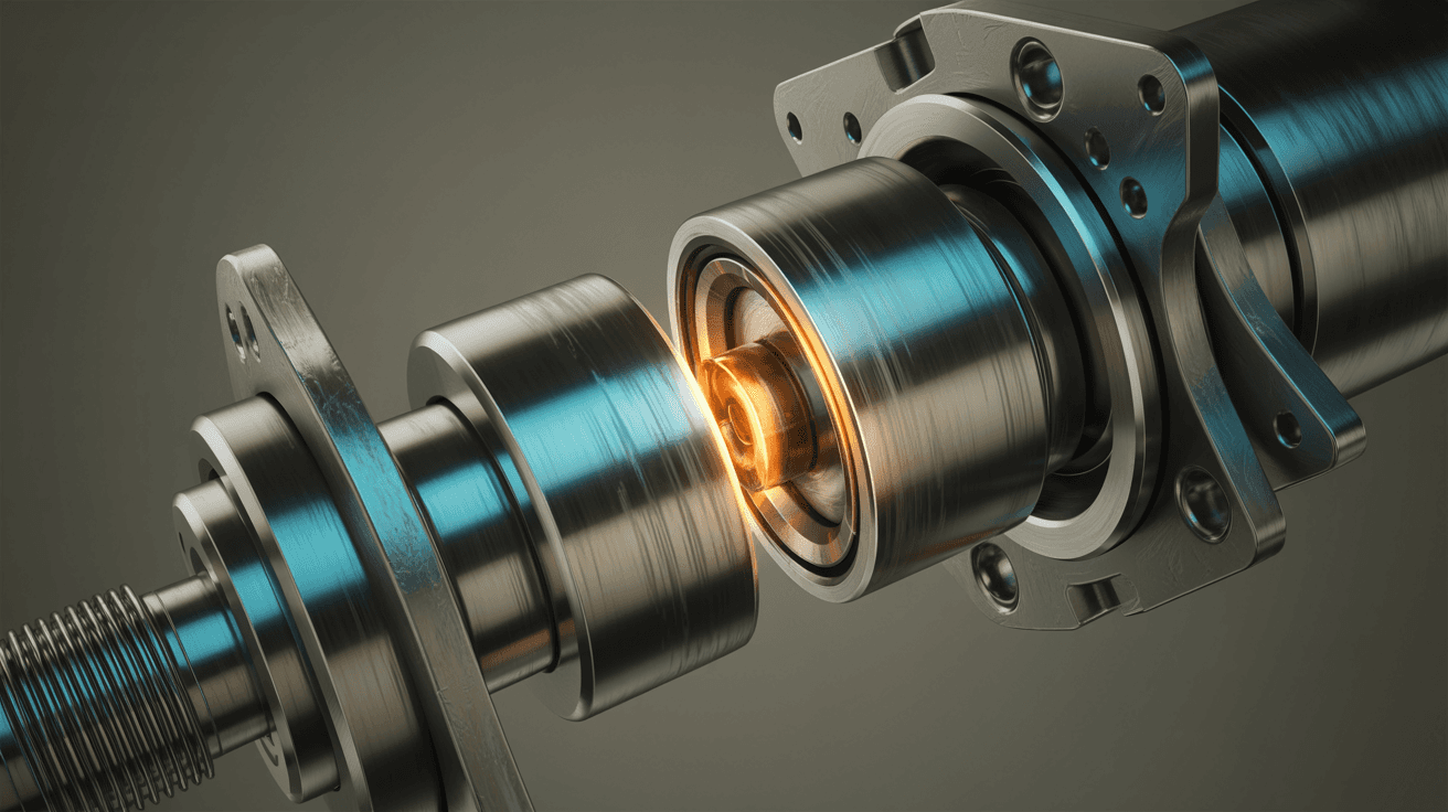
Two components try to occupy the same physical space. On screen the assembly looks finished, the model spins cleanly, and the design review moves on. Then a prototype comes back from the shop and a bracket will not seat, because a bolt head fouls a rib that nobody expected to be in the way. That is an interference, and once it reaches hardware it has already spent time, material, and a place on the schedule.
Interference detection is the practice of finding these clashes in the digital model before anyone cuts metal. Every major CAD system ships some version of it, and yet interference problems still reach manufacturing on a routine basis. The gap is rarely the geometry math. It is a question of when the check runs, how much of the assembly it actually covers, and whether the result reaches the person who can fix it. This guide explains where interference hides in modern assemblies, why traditional clash tools still let collisions through, and how AI is changing the cost of catching a problem early.
The Real Cost of an Interference That Reaches Hardware
Interference comes in two forms. A static interference is a hard clash where two solid bodies overlap in a fixed position. A dynamic interference appears only through motion, when a linkage swings, a piston travels, or a door closes, and two parts that never touch in the modeled pose collide somewhere in the range of movement. A third case is not an overlap at all. It is a clearance violation, where parts do not intersect but sit closer than a service, thermal, or assembly rule allows.
The cost of missing any of these grows quickly the later it is found. A clash caught while modeling costs a few minutes to resolve. The same clash caught at prototype means a reprinted or remachined part and a lost week. Caught at first assembly on a production line, it can stall a build and force an engineering change order that ripples through drawings, tooling, and procurement. The geometry did not change. The price of fixing it did.
This is why interference belongs in the same conversation as broader design quality. Catching a collision is one instance of the wider goal of surfacing problems while they are still cheap, the same goal behind AI-powered design review and the effort to catch CAD mistakes before manufacturing.
IN PRACTICE
What Engineers Are Saying
"With Leo, our team improves design quality, reduces mistakes, and shortens time-to-market."
Uriel B., Field Warfare and Survivability Specialist
Why Traditional Clash Detection Still Lets Collisions Through
The clash tools built into most CAD systems are capable, but the way they fit into real work leaves gaps. The most common reasons a collision survives to the shop floor are the following.
The check is manual and on demand. Someone has to remember to run it, on the right configuration, at the right time. In a busy release cycle that step is easy to skip.
It runs too late. When interference analysis happens only at a final review, the design is already committed and the pressure to ship discourages reopening geometry.
Large assemblies are slow. On an assembly with thousands of components, a full pairwise check can take long enough that engineers narrow the scope, and the parts left out are often where the surprise lives.
Clearance rules are not modeled. Standard clash detection flags overlaps but does not know that a hot component needs a set gap, or that a fastener needs wrench access. Those violations pass silently.
Motion and variants get missed. Dynamic interference across a full range of travel, and clashes that appear only in certain configuration variants, require setup that is often skipped.
The result is a list, not a decision. A raw report of intersecting bodies does not say which clashes matter, which are intentional, or which rule was violated, so triage eats the time the check was supposed to save.
None of this means the underlying math is wrong. It means detection that depends on memory, timing, and manual triage will always leak.
How AI-Powered Interference Detection Works
AI changes interference detection less by inventing new geometry tests and more by removing the human bottlenecks around them. An AI system that reads native CAD geometry can evaluate an assembly continuously rather than waiting for someone to launch a check, and it can reason about the intent of a clearance rather than only the fact of an overlap.
Leo is an AI assistant for mechanical engineers that works as an intelligence layer on top of your existing PDM and PLM environment rather than as a replacement for it. Because it reads the CAD model and connects to the surrounding knowledge base, it can approach interference the way an experienced reviewer would. It looks at how parts relate, checks them against the clearance and access rules that apply to your product, and flags the overlaps that carry real manufacturing or assembly risk.
Three things separate this from a raw clash report. First, the check is tied to requirements, so a small gap that violates a thermal rule is treated differently from a cosmetic overlap. Second, results are prioritized by severity instead of dumped as an undifferentiated list. Third, every flag is backed by a cited source, so an engineer can see which standard or internal rule drove the call and verify it instead of guessing. Leo reports 96 percent accuracy on technical queries and never trains on customer data, which matters when the geometry in question is your intellectual property.
The same engine that understands geometry for interference also supports related checks such as tolerance stack-up analysis, where the question is not whether parts overlap today but whether they will once real tolerances accumulate.
What to Look for in an AI Interference Detection Tool
If you are evaluating tools, the following criteria separate genuine engineering-grade detection from a surface-level checker.
Native geometry understanding. The tool should read the actual CAD model, including B-rep solids, rather than a simplified mesh that loses the precision interference analysis depends on.
Clearance and soft-clash support. It must handle minimum gaps for service access, thermal growth, and assembly, not only hard overlaps.
Full assembly and configuration coverage. It should evaluate large assemblies and their configuration variants without forcing you to shrink the scope.
Requirement awareness. The tool should check against the standards and internal rules that apply to your industry, so results reflect what actually matters for your product.
Explainable, cited results. Every flag should carry a reason and a source you can click and verify, not a bare list of body pairs.
Integration and security. It should connect to your PDM and PLM systems, respect access controls, and keep your data protected. Look for SOC-2 certification and a clear commitment that your models are never used to train shared AI.
Putting Interference Detection Into Your Design Workflow
The value of continuous detection shows up when it is placed at the right moments rather than saved for the end. Three points in the workflow return the most.
During modeling. Running checks as parts are added catches a clash while the designer still has the context to fix it in minutes.
Before release. A full assembly check ahead of sign-off confirms that motion, clearance, and configuration variants are clean before drawings go out.
At every engineering change. A change that looks local often is not. Coupling interference checks with where-used impact analysis shows which downstream assemblies a modified part touches, so a fix in one place does not create a clash somewhere else.
There is a reuse angle as well. When an AI tool already understands the geometry of your library, it can favor existing parts that are known to fit over new geometry that has to be re-checked from scratch, which is the same principle behind avoiding a late DFM surprise. Fewer new parts means fewer new clash paths to worry about.
FAQ
Catch Clashes Before the Shop Floor
See how Leo checks your assemblies against the rules that actually matter.
Leo reads your CAD geometry and connects to your PDM and PLM to flag interference and clearance issues early, with a cited source behind every result. Book a demo to see it on your own assemblies.

#1 New AI Software Globally - G2 2026

Enterprise-grade security

Trusted by world-class engineering teams





